Since I live in a rainy region, I want that temporized mode. It is boring to have to enable manually the wiper in intervals. Let it work in slow mode in low rain condition, cause it to generate noise due the clean rubber working in dry condition.
Typically, the wiper stick behind the steering wheel of most cars here contains 5 (4 if you don’t count the stop mode) position/options (in order) (HTML li does not start from 0, but from 1, damn):
- Stopped (I don’t count )
- Timed wiper – enable wiper to work between T seconds
- Slow Operation mode
- Fast Operation mode
- Window Wash mode (front push to enable the wash and the wiper work for 4 seconds)
- Back Window Wash mode (back push to enable, with toggle function to enable/disable back wiper and wash)
Another option was use of the Window Wash pull switch to enable the operation of the timed mode. There is in the market, toggle relays, to enable the operation of the back window wiper (with a fifth position in the control stick, push to back). However, that could make the use of the wash window hard, and the need of additional relay to enable the toggle, as well as modifications in the relay box to accommodate the new relay. I also don't want that.
So in the spirit of hacker, I so got in the idea of change the original relay, put a microprocessor, and add double click detection on wash switch... and solve my problem, adding functionality and avoiding the elimination of functions!
Since I couldn’t find anything ready on the shelf, I decide develop a solution for such! Initially, I develop the double click and long click detection. Double click activate/deactivate the temporized mode. Long click still turn on the washer/wiper for some seconds as original. In further increments I enable the variable wiper work mode, without the use of any additional switches!
Below I present all the development of such device, that I chose share! The decisions, steps involved, block diagrams, state machines and everything else. I start checking how wiper/wash relay is plugged into relay box and how it works. Typical wiper/wash relay is based on U641B chip. It is an 8 pin analog dip chip which care of temporized wiper/wash operation. Figure 1 show the details of typical circuit. This image is from Atmel datasheet. I believe that other companies manufacture it too.


Bosch relays use this chip. So, in order to create my solution, I should develop a substitute for such chip. I had two main option to do that. With sequential logic, or with software. Since I am a prominent programmer, and love assembler I did it in software. I had in hands during the development some Microchip PIC microcontrollers, 16f677a. So I develop the initial idea on them. When the development got in a nice point, I decide to move to a small chip, which could fit inside the small relay closure without many changes. Adjusting the code and moved to pic12f675 (8 pin DIP) chip, which was the most easily found on stores nearby.
However, the program could be, with some work, easily adapted to the less expensive device from microchip, as the 10f200. But to use this chip, you have to get rid of the interruption routines, which are not present in 10f200 line. So a move in that direction could need changes (resembles almost and Atari programming’s counting cycles to get accurate timing ).
Basic block ideas
The initial ideas born as block diagrams to a state machine, and are presented below. The basic block diagram born somewhere in the process. So I will present the basic state machine to control, block diagram, and the top state machine. (there are 2 main state machines).With the basic idea of the device, I wrote down on paper the details which I wish that system should had:
- The chip should work normally on systems which had the timed switch.
- The wash mode should work normally, activating the wiper continuously for 4 seconds (S) when the wash switch pass 0.6 seconds ON (LONG CLICK). (not enable the wash mode if is bellow this)
- The double click should be detected efficiently and naturally (DCLICK). A time window should be efficient in detect variables double clicks. The first click must be below 0.6 seconds, to not cause ambigueties.
- The enable of temporized wiper mode (TEMPO) by the default switch should overthrow the double click mode.
- The double click should not have influence when the system was working in tempo wiper mode by the default switch.
- The 3th click on the wash, right after the double click should control the interval between windows clean, up to a 15 second window. Is nothing happen in this time, the system will work in 15 second interval, until user double clicks again to disable the temporized mode.

These block shown the the kind of messages that I should gen and thread. The overall block diagram of the system is in figure 3.

I needed still establish the block that process the generated the events from the initial event machine. The events are:
• CLICK – user click the wash switch, but release before TMaxOn seconds (0.6 seconds). This event is toggle each time it happens, but it should be cleaned when treated by the Main Event state machine.
• LONG_CLICK – user click greater than TMaxOn. This event is set and clean by the Event Generator.
• DOUBLE_CLICK – double click, recognized when click is less than TMaxOn and off interval is less than TMaxOff. This event is toggle each time the event generator identifies it
• TEMPO – user activate the tempo switch The state machine that controls such behavior is presented in figure 4. This event disable other events, but the LONG_CLICK.
There are also some time diagrams. The CLICK event:


The DOUBLE CLICK


The debouching used is in the diagram of figure 4 and was explained in one post I did some years ago. The outside numbers represent the signal coming from the outside world. The inside numbers in the diagram represent the signal passed to the next block inside the process. By the way, all the diagrams were made with DIA program. Very nice and free!
The event handling is done by this state machine:

They state machines for handling the messages are split in two, because Wash is run in parallel with the Timed Wiper mode. However they run in the same mainloop of the program.
Main Program Details
The program was all implemented in PIC assembler. The overall description of the development of the program is the follow:
- main event handling: run in the main loop, since it attend the events from the event generation process.
- event generation process: use an timed routine, with execute every 20ms, and get key state from the debounce.
- debounce routine: runs at 5ms, also in timed routine, treating switches states.
- A timer counter of the PIC is configured to increase each 256ms, and top byte only is used, being used by event management, who can be reset,set and read it. I believe I can eliminate this. I even do not remember if I already don't sweep this out.
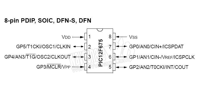
Some tips about the pins used in this version of the code, that is adjusted for PIC12F675.
All bits are in PORTA (or GP pins as Microchip like call):
GP0 (in) - wash key (PIN 7)
GP1 (in)- tempo key (PIN 6)
GP2 (out) - out to driver (PIN 5)
GP5 (out) - was used to check the itnerruption frequency
I'm pasting this picture of the pic from other site. It may get out of work eventually...
CODE LINK - I used dropbox, but if it does not work, tell me.
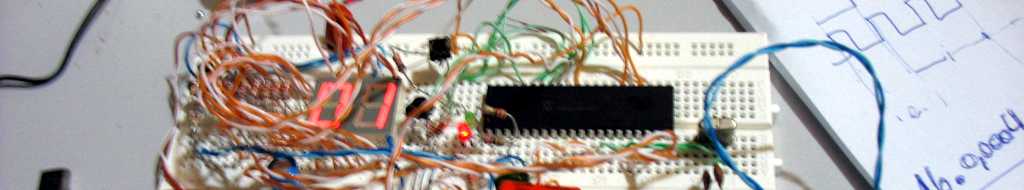
The photo below was one of the first version of the device, already with PIC12F675. A pin was used to generate a wave signal, who is commented in the start of the interruption routine, to know if the interruption routine was running fine, in desired time interval. It was =). To clock everything, was used the internal oscillator of the chip, which run in 4MHz. It is pretty stable for this use.

The basic schematic for the circuit is below. Sorry the poorer details in schematic. The 2 power supplies are there just to remember that the 12V from the battery need to be down converted, either with a Zener or a 7805. I used a Zener for some time, as the current need for the PIC are pretty low. The relay is pluged in 12V supply, so a 1K or higgher resistor is required in the base of the NPN transistor. The signal of the keys, S1 and S2, need to be reduce, in order to drive the input pins too. If no, you can kill the PIC chip. I used a simple divisor, with 2k2 and 4k7 resistors.

A etched some boards for this circuit at home. I could not find anymore the photos of the other versions and prototypes I did. I manufacture also some boards also in a professional company. If someone want, I have them available for any value, for use. I even try some different configurations for the boards. The top left I etched home, but it is not the one I send to professional etching. This board version uses Zener, but the new one use 7805 package in TO-72.

Final Considerations
This project was done by me in 2010. Is born because the lack of functionally in our cars. It was a very nice develop process, for me. I take less than a month to get ready. I spent many time looking to the possibility of manufacture this, but I give up. I learn some interesting things with this project too.
At that time, I try to sell the idea to some of the manufactures of relays in the country. No one wanted. One company get in touch with me, but they simple give up. So I got really unmotivated at time. I stop build any project.
I decide to share it soon after, but I never felt that it was ready to share. Well, I am sharing it now. May be some mistakes in the text (sorry the poor English). Please, tell me if you want to know something, or if I wrote some really bad. I really believe that the idea can be re-purposed. The first thing that came into my mind is that the double click could be used as garage opener option against ugly switches in car panel. Even other uses.
I am glad in share this with the community. I hope that you enjoyed it! Specially reading the code!